|
|
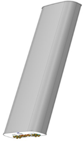
NWAV™ X-Pol 14-Port Antenna
|
|
|
-
Fast Roll Off (FRO™) azimuth beam pattern improves Intra- and Inter-cell SINR
-
Combination of Hex Port Antenna with integrated 5G 3.5 GHz 8T8R beamforming capability
-
Optimized antenna array design for all 3.5 GHz beamforming combinations
-
Maintains existing low and mid band RF performance
- New optimized form factor for reduced wind loading
-
Lower antenna weight with new Integrated RF distribution design
- Excellent passive intermodulation (PIM) performance reduces harmful interference.
-
Fully integrated internal (iRETs) with SBT for independent RET control on all bands
|

|
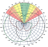
| The horizontal beam produced by Fast Roll-Off (FRO) technology increases the Signal to Interference & Noise Ratio (SINR) by eliminating overlap between sectors
.
|
| Non-FRO antenna
|
Large traditional antenna pattern overlap creates harmful interference. |
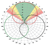
JMA FRO antenna
|
|
JMA’s FRO antenna pattern minimizes overlap, thereby minimizing interference. |
|
| LTE throughput |
SINR |
Speed
(bps/Hz) |
Speed increase |
CQI |
|
| Excellent |
>18 |
>4.5 |
333+% |
8-10 |
|
| Good |
15-18 |
3.3-4.5 |
277% |
6-7 |
|
| Fair |
10-15 |
2-3.3 |
160% |
4-6 |
|
|
|
| The LTE radio automatically selects the best throughput based on measured SINR. |
|
| Frequency bands, MHz |
698-806 |
806-894 |
1695-1880 |
1850-1990 |
1920-2200 |
| Polarization |
± 45° |
± 45° |
| Gain over all tilts, dBi |
14.1 |
15.1 |
17.2 |
17.6 |
18.1 |
| Horizontal beamwidth (HBW), degrees1 |
52 |
46 |
48 |
44 |
41 |
| Front-to-back ratio, @180°, dB
|
>30.0 |
>29.0 |
>28.0 |
>26.0 |
>25.0 |
| X-Pol discrimination (CPR) at boresight, dB
|
>20.0 |
>17.0 |
>19.0 |
>21.0 |
>21.0 |
| Vertical beamwidth (VBW), degrees1 |
18.3 |
16.1 |
8.0 |
7.2 |
7.0 |
| Electrical downtilt (EDT) range, degrees |
2-16 |
0-9 |
| First upper side lobe (USLS) suppression, dB1 |
≤-16.0 |
≤-16.0 |
≤-16.0 |
≤-16.0 |
≤-16.0 |
| Cross-polar isolation, port-to-port, dB1 |
25 |
25 |
25 |
25 |
25 |
| Max VSWR / return loss, dB |
1.5:1 / -14.0 |
1.5:1 / -14.0 |
| Max passive intermodulation (PIM), 2x20W carrier, dBc |
-153 |
-153 |
| Max input power per any port, watts |
300 |
250 |
| Total composite power all ports (1-14), watts
|
1500 |
1 Typical value over frequency and tilt
| Frequency bands, MHz |
3700-4200 |
| Gain over all tilts, dBi |
15.7 |
| Horizontal beamwidth (HBW), degrees1 |
85 |
| Horizontal beam width tolerance, degrees
|
±5 |
| Front-to-back ratio, @180°, dB
|
27 |
| Vertical beamwidth (VBW), degrees1 |
7.5 |
| Vertical beam width tolerance, degrees
|
±0.3 |
| Beam tilt, degrees |
2-12 |
| First upper side lobe (USLS) suppression, dB1 |
15 |
| Coupling level, Amp, Antenna port to Cal port, dB
|
26 |
| Coupling level, max Amp Δ, Antenna port to Cal port, dB
|
±0.7 |
| Coupler, max Amp Δ, Antenna port to Cal port, dB
|
0.65 |
| Coupler, max Phase Δ, Antenna port to Cal port, degrees
|
4 |
| Cross-polar isolation, port-to-port, dB1 |
25 |
| Isolation, Inter-band, dB
|
25 |
| Max VSWR / return loss, dB |
1.5 / -14.0 |
| PIM, 3rd Order, 2 x 20 W, dBc
|
-145
|
| Max input power per any port at 50 °C, watts |
75 |
1 Typical value over frequency and tilt
| Frequency bands, MHz |
3700-4200 |
| Gain over all tilts, dBi |
21.2 |
| Horizontal beamwidth (HBW), degrees1 |
65 |
| Horizontal beamwidth tolerance, degrees |
±4 |
| Vertical beamwidth (VBW), degrees1 |
7.5 |
| Vertical beamwidth tolerance, degrees |
±0.3 |
| First upper side lobe (USLS) suppression, dB1 |
<-16 |
| Frequency bands, MHz |
3700-4200 |
| Steered 0° gain, dBi |
21.2 |
| Steered 0° Gain tolerance, dBi
|
±0.6 |
| Steered 0° Beamwidth, Horizontal, degrees
|
24 |
| Steered 0° CPR at beampeak, dB
|
18 |
| Steered 0° Horizontal Sidelobe, dB
|
12 |
| Steered 30° Gain, dBi (max)
|
20.5 |
| Steered 30° Gain tolerance, dBi
|
±0.6 |
| Steered 30° Gain, dBi
|
20.7 |
| Steered 30° Beamwidth, Horizontal, degree
|
22 |
| Steered 30° CPR at beampeak, dB
|
18 |
| Steered 30° Horizontal Sidelobe, dB
|
10 |
| Frequency bands, MHz |
3700-4200 |
| Gain over all tilts, dBi |
19.8 |
| Horizontal beamwidth (HBW), degrees1 |
33 |
| First upper side lobe (USLS) suppression, dB1 |
15 |
Beamforming weighting table available upon request
| Antenna model
|
Description
|
| MX14FRO445-01
|
4F X- Pol 14 Port FRO 45⁰ 2-16⁰/ 0-9⁰/ 2-12⁰ RET, 4.3-10 & SBT
|
| Optional accessories
|
| AISG cables
|
M/F cables for AISG connections |
| PCU-1000 RET controller
|
Stand-alone controller for RET control and configurations |
| 91900314-03
|
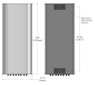
Dual Mount Bracket (see 91900314 bracket document for details)
|
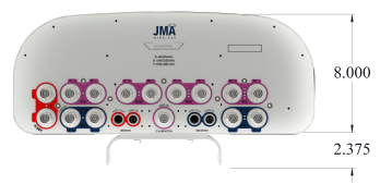
| Dimensions height/width/depth, inches (mm) |
55.0/ 20.0/ 8.0 (1397/ 508.0/ 203.2) |
| Shipping dimensions length/width/height, inches (mm)
|
65/ 23.8/ 14.5 (1651/ 605/ 368) |
| No. of RF input ports, connector type, and location |
14 x 4.3-10 female, bottom |
| Calibration interface port, connector type, and location |
1 x 4.3-10 female, bottom |
| RF connector torque |
96 lbf·in (10.85 N·m or 8 lbf·ft) |
| Net antenna weight, lb (kg) |
65 (29.5) |
| Shipping weight, lb (kg)
|
103 (46.7) |
| Antenna mounting and downtilt kit included with antenna
|
91900318 |
| Net weight of the mounting and downtilt kit, lb (kg)
|
18 (8.18) |
| Range of mechanical up/down tilt
|
-2° to 12° |
| Rated wind survival speed, mph (km/h) |
150 (241) |
| Frontal and lateral wind loading @ 150 km/h, lbf (N) |
98.7 (439.0), 45.7 (203.3) |
| EPA frontal and lateral, ft2, (m2) |
4.4 (0.41), 2.1 (0.20) |
|
|
| RET location
|
Integrated into antenna
|
| RET interface connector type
|
8-pin AISG connector per IEC 60130-9
or RF port bias-t |
| RET connector torque |
Min 0.5 N·m to max 1.0 N·m (hand pressure & finger tight) |
| RET interface connector quantity
|
2 pairs of AISG male/female connectors and 3 RF port bias-ts |
| RET interface connector location
|
Bottom of the antenna
|
| Total no. of internal RETs 698-894 MHz |
1 |
| Total no. of internal RETs 1695-2200 MHz
|
1 |
| Total no. of internal RETs 3700-4200 MHz |
1 |
| RET input operating voltage, vdc
|
10-30 |
| RET max power consumption, idle state, W
|
≤ 2.0
|
| RET max power consumption, normal operating conditions, W
|
≤ 13.0
|
| RET communication protocol
|
AISG 2.0 / 3GPP
|
| The R1 and B1/B2 RET devices can be controlled via either the designated external AISG connectors or the RF smart bias-t ports. The P1 RET devices can be controlled via the RF smart bias-t port only as shown below:
|
|
| Band
|
RF port
|
| 1695-2200 |
3-6 |
|
|
| Band
|
RF port
|
| 3700-4200 |
7-14 |
|
|
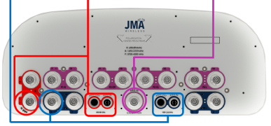
|
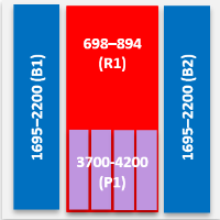
4 sets of radiating arrays
R1: 698-894 MHz
B1: 1695-2200 MHz
B2: 1695-2200 MHz
P1: 3700-4200 MHz
|
| Band |
RF port
|
| 698-894
|
1-2
|
| 1695-2200
|
3-4 |
| 1695-2200
|
5-6 |
| 3700-4200 |
7-14 |
|
|
V5.0
01/15/26
