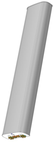
MX08FRO465-20
|
NWAV™ X-Pol 8-Port Antenna
|
|
|
-
Fast Roll Off (FRO™) azimuth beam pattern improves Intra- and Inter-cell SINR
-
Excellent passive intermodulation (PIM) performance reduces harmful interference.
-
Fully integrated (iRETs) with independent RET control for low and mid bands for ease of network optimization
-
SON-Ready array spacing supports beamforming capabilities.
|

|
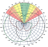
| The horizontal beam produced by Fast Roll-Off (FRO) technology increases the Signal to Interference & Noise Ratio (SINR) by eliminating overlap between sectors
.
|
| Non-FRO antenna
|
Large traditional antenna pattern overlap creates harmful interference. |
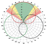
JMA FRO antenna
|
|
JMA’s FRO antenna pattern minimizes overlap, thereby minimizing interference. |
|
| LTE throughput |
SINR |
Speed
(bps/Hz) |
Speed increase |
CQI |
|
| Excellent |
>18 |
>4.5 |
333+% |
8-10 |
|
| Good |
15-18 |
3.3-4.5 |
277% |
6-7 |
|
| Fair |
10-15 |
2-3.3 |
160% |
4-6 |
|
|
|
| The LTE radio automatically selects the best throughput based on measured SINR. |
|
| Frequency bands, MHz |
617-698 |
698-894 |
1695-1880 |
1850-1990 |
1920-2200 |
| Polarization |
± 45° |
± 45° |
| Gain over all tilts, max, dBi |
11.8 |
13.1 |
16.5 |
17.0 |
17.2 |
| Horizontal beamwidth (HBW), degrees1 |
68 |
62 |
64 |
61 |
62 |
| Front-to-back ratio, co-polar power @180°± 30°, dB
|
>27 |
>29 |
>32 |
>35 |
>32 |
| Vertical beamwidth (VBW), degrees1 |
19.5 |
16.5 |
8.0 |
7.5 |
6.9 |
| Electrical downtilt (EDT) range, degrees |
2-16 |
2-12 |
| First upper side lobe (USLS) suppression, dB1 |
≤-16.0 |
≤-16.5 |
≤-18.0 |
≤-18.0 |
≤-18.0 |
| Minimum cross-polar isolation, port-to-port, dB1 |
25 |
25 |
25 |
25 |
25 |
| Max VSWR / return loss, dB |
1.5:1 / -14.0 |
1.5:1 / -14.0 |
| Max passive intermodulation (PIM), 2x20W carrier, dBc |
-153 |
-153 |
| Max input power per any port, watts |
300 |
250 |
| Total composite power all ports (1-8), watts2 |
1500 |
1 Typical value over frequency and tilt
2 Power rated up to +55 °C
| Frequency bands, MHz |
617-698 |
698-894 |
1695-1880 |
1850-1990 |
1920-2200 |
| Average gain over all tilts, dBi (Gain Tolerance) |
11.3±0.5 |
13.2±0.5 |
16.1±0.4 |
16.6±0.4 |
16.8±0.5 |
| Horizontal beamwidth tolerance (HBW), degrees1 |
±5 |
±6.5 |
±5.5 |
±3.5 |
±5.0 |
| Vertical beamwidth tolerance (VBW), degrees |
±0.3 |
±0.3 |
±0.3 |
±0.3 |
±0.3 |
| Front-to-back ratio, co-polar power @180°± 30°, dB
|
>27 |
>25 |
>25 |
>26 |
>24 |
| X-Pol discrimination (CPR) at boresight, dB |
>20 |
>19.5 |
>17.5 |
>19 |
>19.5 |
| First upper side lobe (USLS) suppression boresight to 20°, dB1 |
≤-16 |
≤-15 |
≤-16 |
≤-16 |
≤-16 |
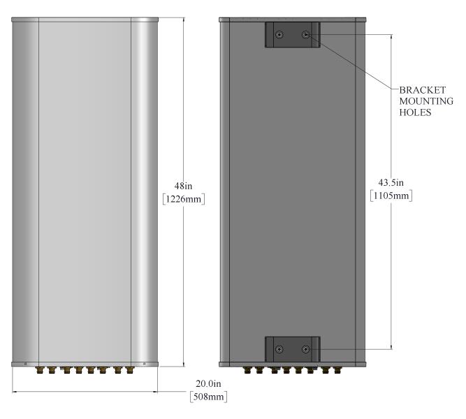
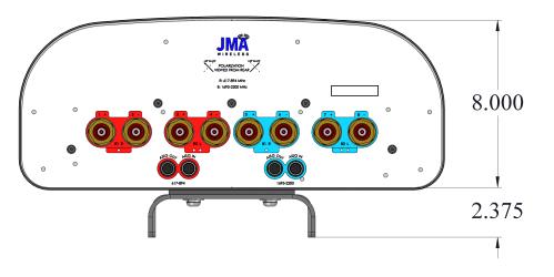
| Dimensions height/width/depth, inches (mm) |
48/ 20.0/ 8.0 (1219/ 508.0/ 203.2) |
| Shipping dimensions length/width/height, inches (mm)
|
53.3/ 23.8/ 14.5 (1353.8/ 605/ 368) |
| No. of RF input ports, connector type, and location |
8 x 4.3-10 female, bottom |
| RF connector torque |
96 lbf·in (10.85 N·m or 8 lbf·ft) |
| Net antenna weight, lb (kg) |
51.3 (23.27) |
| Shipping weight, lb (kg)
|
89.3 (40.5) |
| Antenna mounting and downtilt kit included with antenna
|
91900318 |
| Net weight of the mounting and downtilt kit, lb (kg)
|
18 (8.2) |
| Range of mechanical up/down tilt
|
-2° to 12° |
| Rated wind survival speed, mph (km/h) |
150 (241) |
| Frontal and lateral wind loading @ 150 km/h, lbf (N) |
88 (391.44), 40 (177.93) |
| Effective projected area @ 150 km/h (EPA), frontal, sq ft |
3.9 |
|
| Bottom view
|
|
| RET location
|
Integrated into antenna
|
| RET interface connector type
|
8-pin AISG connector per IEC 60130-9 |
| RET connector torque |
Min 0.5 N·m to max 1.0 N·m (hand pressure & finger tight) |
| RET interface connector quantity
|
2 pairs of AISG male/female connectors |
| RET interface connector location
|
Bottom of the antenna
|
| Total no. of internal RETs 617-894 MHz |
1 |
| Total no. of internal RETs 1695-2200 MHz
|
1 |
| RET input operating voltage, vdc
|
10-30 |
| RET max power consumption, idle state, W
|
≤ 2.0
|
| RET max power consumption, normal operating conditions, W
|
≤ 10.0
|
| RET communication protocol
|
Hardware AISG 3.0; firmware AISG 2.0, field-upgradable to AISG 3.0 |
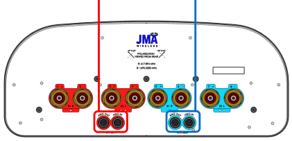
| Each RET device can be controlled via the designated external AISG connector as shown below: |
|
|
| Band
|
RF port
|
| 1695-2200
|
5-8
|
|
|
|
4 sets of radiating arrays
R1: 617-894 MHz
R2: 617-894 MHz
B1: 1695-2200 MHz
B2: 1695-2200 MHz
|
| Band |
RF port
|
| 617-894
|
1-2
|
| 617-894 |
3-4
|
| 1695-2200 |
5-6
|
| 1695-2200 |
7-8
|
|
|
V4.0
01/15/26
