| Frequency bands, MHz |
3700-4200 |
| Gain, dBi |
17.1 |
| Horizontal beamwidth (HBW), degrees |
85 |
| Horizontal beamwidth tolerance, degrees |
±5 |
| Front-to-back ratio, co-polar power @180°± 30°, dB
|
27 |
| Vertical beamwidth (VBW), degrees1 |
5.5 |
| Vertical beamwidth tolerance, degrees |
±0.3 |
| Remote electrical downtilt (EDT) range, degrees |
2-12 |
| First upper side lobe (USLS) suppression, dB1
|
15 |
| Coupling level, Amp, Antenna port to Cal port, dB
|
26 |
| Coupling level, max Amp Δ, Antenna port to Cal port, dB
|
±0.6 |
| Coupler, max Amp Δ, Antenna port to Cal port, dB
|
0.65 |
| Coupler, max Phase Δ, Antenna port to Cal port, degrees
|
4 |
| Cross-polar isolation, port-to-port, dB1 |
25 |
| Max VSWR / return loss, dB |
1.5:1 / -14.0 |
| Max passive intermodulation (PIM), 2x20W carrier, dBc |
-145 |
| Max input power per port at 50 °C, watts |
75 |
1 Typical value over frequency and tilt
| Frequency bands, MHz |
3700-4200 |
| Gain over all tilts, dBi |
22.5 |
| Horizontal beamwidth (HBW), degrees1 |
65 |
| Horizontal beamwidth tolerance, degrees |
±6 |
| Vertical beamwidth (VBW), degrees1 |
5.5 |
| Vertical beamwidth tolerance, degrees |
±0.3 |
| First upper side lobe (USLS) suppression, dB1 |
<-16 |
| Frequency bands, MHz |
3700-4200 |
| Steered 0° gain, dBi |
22.5 |
| Steered 0° Gain tolerance, dBi
|
±0.6 |
| Steered 0° Beamwidth, Horizontal, degrees
|
22 |
| Steered 0° CPR at beampeak, dB
|
18 |
| Steered 0° Horizontal Sidelobe, dB
|
12 |
| Steered 30° Gain, dBi (max)
|
21.8 |
| Steered 30° Gain tolerance, dBi
|
±0.6 |
| Steered 30° Gain, dBi
|
21 |
| Steered 30° Beamwidth, Horizontal, degree
|
22.2 |
| Steered 30° CPR at beampeak, dB
|
18 |
| Steered 30° Horizontal Sidelobe, dB
|
10 |
| Frequency bands, MHz |
3700-4200 |
| Gain over all tilts, dBi |
21.8 |
| Horizontal beamwidth (HBW), degrees1 |
32 |
| First upper side lobe (USLS) suppression, dB1 |
15 |
Beamforming weighting table available upon request
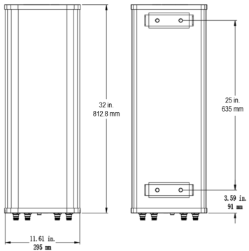
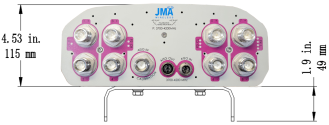
| Dimensions height/width/depth, inches (mm) |
32.0/ 11.6/ 4.53 (812.8/ 295/ 115) |
| Shipping dimensions length/width/height, inches (mm)
|
37.0/ 16.9/ 11.8 (939.8/ 430/ 300) |
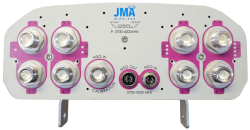
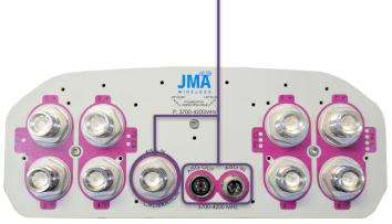
| No. of RF input ports, connector type, and location |
8 x 4.3-10 female, bottom |
| Calibration interface port, connector type, and location |
1 x 4.3-10 female, bottom |
| RF connector torque |
96 lbf·in (10.85 N·m or 8 lbf·ft) |
| Net antenna weight, lb (kg) |
23.2 (10.52) |
| Weight with supplied pipe mount bracket, lb (kg)
|
26.5 (12.02)
|
| Shipping weight, lb (kg)
|
49.1 (22.27)
|
| Rated wind survival speed, mph (km/h) |
56.9 (253.1). 10.9 (48.5) |
| Frontal and lateral wind loading @ 150 km/h, lbf (N) |
56.9 |
| EPA frontal and lateral, ft2, (m2) |
2.6 (0.24), 0.5 (0.05) |
|
|
| Antenna model
|
Description
|
| MX08FIT265-01
|
32-inch 8T8R beamforming antenna, 3700-4200 MHz with RET
|
| Mounting kit (included)
|
91900330 BRACKET KIT, range of mechanical up/down tilt -2° to 12° |
| Optional accessories
|
| AISG cables
|
M/F cables for AISG connections |
| PCU-1000 RET controller
|
Stand-alone controller for RET control and configurations |
| RET location
|
Integrated into antenna
|
| RET interface connector type
|
8-pin AISG connector per IEC 60130-9
or RF port Bias-T |
| RET connector torque |
Min 0.5 N·m to max 1.0 N·m (hand pressure & finger tight) |
| RET interface connector quantity
|
1 pair of AISG male/female connectors and 1 RF port Bias-T |
| RET interface connector location
|
Bottom of the antenna
|
| Total no. of internal RETs |
1 |
| RET input operating voltage, vdc
|
10-30 |
| RET max power consumption, idle state, W
|
≤ 2.0
|
| RET max power consumption, normal operating conditions, W
|
≤ 13.0
|
| RET communication protocol
|
AISG 2.0 / 3GPP
|
| Each RET device can be controlled either via the designated external AISG connector or RF port as shown below: |
|
| RET device |
Band
|
RF port
|
| 1
|
3700-4200
|
1-8 |
|
|
|
1 set of radiating arrays
P1: 3700-4200 MHz
|
| Band |
RF port
|
| 3700-4200 |
1-8
|
|
|
V6.0
01/15/26