|
|

|
12-port panel antenna from 698-5925 MHz 2F panel antenna, 12 ports: 2 ports 698-960, 4 ports 1695-2690 MHz, 4 ports 3550-3700 MHz, and 2 ports 5150-5925 MHz* |
|
|---|---|
* This antenna meets current U-NII-1 requirements for gain and upper side lobe pattern characteristics with Compliance Testing of Unlicensed National Information Infrastructure (U-NII) Devices - Part 15, Subpart E. Compliant to 789033 D02 General U-NII Test Procedures v01r04. |
|

| Electrical specification (min/max) | Ports 1, 2 | Ports 3, 4, 5, 6 | ||||||
|---|---|---|---|---|---|---|---|---|
| Frequency bands, MHz | 698-798 | 824-894 | 880-960 | 1695-1880 | 1850-1990 | 1920-2180 | 2300-2400 | 2496-2690 |
| Polarization | ± 45° | ± 45° | ||||||
| Average gain, dBi | 9.7 | 10.1 | 10.5 | 13.1 | 13.6 | 13.8 | 14.1 | 14.2 |
| Horizontal beamwidth (HBW), degrees1 | 69° | 69° | 69° | 68° | 65° | 64° | 62° | 59° |
| Vertical beamwidth (VBW), degrees1 | 41° | 39° | 37° | 16.8° | 16.7° | 15.8° | 13.5° | 11.7° |
| Fixed electrical downtilt (EDT), degrees | 2° | 0 or 6° | ||||||
| Cross-polar isolation, port-to-port, dB1 | 25 | 25 | ||||||
| Max VSWR / return loss, dB | 1.5:1 / -14.0 | 1.5:1 / -14.0 | ||||||
| Max PIM (3rd order, 2x20W) dBc | -153 | -153 | ||||||
| Maximum input power port, watts | 100 | 150 | ||||||
| Electrical specification (min/max) |
|
|||
|---|---|---|---|---|
| Frequency bands, MHz | 3550-3700 | 5150-5925 | ||
| Polarization | ± 45° | ± 45° | ||
| Average gain, dBi | 14.8 | 5 | ||
| Horizontal beamwidth (HBW), degrees1 | 45° | 48° | ||
| Vertical beamwidth (VBW), degrees1 | 9° | 24° | ||
| Fixed electrical downtilt (EDT), degrees | 0° | |||
| Cross-polar isolation, port-to-port, dB1 | 22 | 25 | ||
| Max VSWR / return loss, dB | 1.5:1 / -14.0 | 1.5:1 / -14.0 | ||
| Max PIM (3rd order, 2x20W) dBc | N/A | |||
| Maximum input power, watts | 50 | 10 | ||
| 1 Typical value over frequency. | Note: Vertical beam upper side lobe at 5150-5925 MHz < -15 dB at > 30° above horizon |
| Mechanical specifications | |
|---|---|
| Dimensions height/width/depth, inches (mm) |
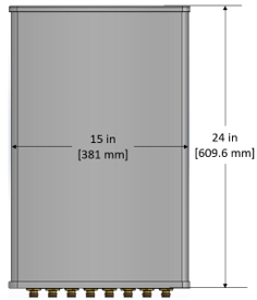
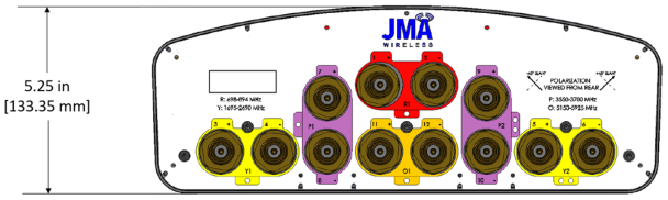
24/ 15/ 5.25 (610/ 381/ 134) |
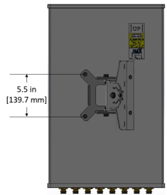
| No. of RF input ports, connector type, and location | 12 x 4.3-10 female, back |
| RF connector torque | 96 lbf·in (10.85 N·m or 8 lbf·ft) |
| Net antenna weight, lb (kg) | 12.3 (5.6) |
| Weight with supplied pipe mount bracket, lb (kg) | 17.4 (7.9) |
| Shipping weight, lb (kg) | 23.3 (10.6) |
| Rated wind survival speed, mph (km/h) | 150 (241) |
| Frontal wind loading @ 150 km/h, lbf (N) | 30 (133) |
| Equivalent flat plate @ 100 mph and Cd=2, sq ft | 0.34 |
| Installation instructions | DX-*/SX-*/IX-* Antenna Mounting Instructions and Kits 81900511 |
| Weep hole drilling instructions | DX-*/SX-*/IX-* Antenna Weep Hole Modification Guide |
| Front view | Back view |
|---|---|
 |
|
| Bottom view |
|---|
|
|
| Ordering information | |
|---|---|
| Antenna model | Description |
| DX12FRO260-20 | 2F panel antenna, 12 ports, (2) 698–960 two degrees EDT, (4) 1695-2690 zero degrees EDT, (4) CBRS zero degrees EDT, (2) LAA zero degrees EDT |
| DX12FRO260-26 | 2F panel antenna, 12 ports, (2) 698–960 two degrees EDT, (4) 1695-2700 six degrees EDT, (4) CBRS zero degrees EDT, (2) LAA zero degrees EDT |
| Mounting kit (included) | 91900324 articulating bracket with X- and Y-axis adjustments and rotation |
V3.0
| ©2026 JMA Wireless. All rights reserved. All products, company names, brands, and logos are trademarks™ or registered® trademarks of their respective holders. All specifications are subject to change without notice. +1 315.431.7100 customerservice@jmawireless.com |