|
|

|
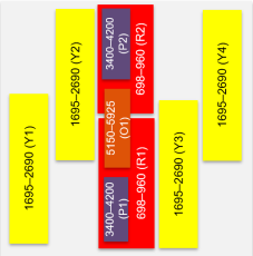
18-port cylinder antenna 698-5925 MHz: 4 ports 698-960, 8 ports 1695-2690 MHz, 4 ports 3400-4200 MHz, and 2 ports 5150-5925 MHz |
||
|---|---|---|
|
|
|


| GPS band | Low band | Mid band | CBRS/LS6 | LAA band | ||||||
|---|---|---|---|---|---|---|---|---|---|---|
| Frequency bands, MHz | 1575.42 | (2x) 696-960 | (4x) 1695-2690 | (2x) 3400-4200 | (1x) 5150-5925 | |||||
| Array | -- |
 R1 R1 |
R2 |
 Y1 Y1 |
Y2 |
Y3 |
Y4 |
 P1 P1 |
P2 |
 O1 O1 |
| Connector | 1 PORT | 4 PORTS | 8 PORTS | 4 PORTS | 2 PORTS | |||||
| Polarization | RH CIR. | XPOL | XPOL | XPOL | XPOL | |||||
| Horizontal beamwidth (HBW), degrees1 | -- | 360 | 360 | 360 | 360 | |||||
| Electrical downtilt (EDT), degrees1 | -- | 0 | 2, 4, 6 | 0 | 0 | |||||
| Configuration | Omni antenna with integrated GPS unit | |||||||||
| Connector type | (18x) 4.3-10 female and (1x) N-type female for GPS | |||||||||
| Dimensions, in. (mm) | 24.0/ 14.6 (609.6/ 370.8) | |||||||||
| Maximum composite power, watts (all ports) | 1000 | |||||||||
| Radome color | Gray (Pantone 420C) | Brown (Pantone 476C) | Black (RAL 9011) |

|

|

|
| Electrical specifications Low Band R1 R2 |
|
|---|---|
| Frequency range, MHz | (2x) 698-960 |
| Polarization | (2x) ± 45° |
| Gain, BASTA, dBi | 2.7 ± 0.5 |
| Gain, MAX, dBi | 3.2 |
| Horizontal beamwidth (HBW), 3 dB, degrees1 | 360 |
| Vertical beamwidth (VBW), 3dB, degrees1 | 76.5 |
| Electrical downtilt (EDT), degrees | 0 |
| Impedance, ohms | 50 |
| VSWR | ≤ 1.5:1 |
| PIM, 2x20W carrier, dBc | < -153 |
| Isolation, intra-band, dB | >25 |
| Isolation, inter-band, dB | >28 |
| Isolation, network-network, dB | >30 |
| Input power per port, watts | 150 |
| Electrical specifications Mid Band Y1 Y2 Y3 Y4 |
||||
|---|---|---|---|---|
| Frequency range, MHz | (4x) 1695-2690 | |||
| Frequency sub-range, MHz | 1695-1880 | 1850-1990 | 1920-2200 | 2300-2690 |
| Polarization | (4x) ± 45° | |||
| Gain, BASTA, dBi | 6.6 ± 0.5 | 6.7 ± 0.5 | 7.1 ± 0.7 | 8.1 ± 0.5 |
| Gain, MAX, dBi | 7.1 | 7.3 | 7.8 | 8.6 |
| Horizontal beamwidth (HBW), 3 dB, degrees1 | 360 | 360 | 360 | 360 |
| Vertical beamwidth (VBW), 3dB, degrees1 | 30.3 | 28.0 | 26.1 | 22.9 |
| Electrical downtilt (EDT), degrees | 2 or 4 or 6 | |||
| Impedance, ohms | 50 | |||
| VSWR | ≤ 1.5:1 | |||
| PIM, 2x20W carrier, dBc | < -153 | |||
| Isolation, intra-band, dB | >25 | |||
| Isolation, inter-band, dB | >28 | |||
| Isolation, network-network, dB | >30 | |||
| Input power per port, watts | 125 | |||
| Electrical specification CBRS/LS6 P1 P2 |
|
|---|---|
| Frequency range, MHz | (2x) 3400-4200 |
| Polarization | (2x) ± 45° |
| Gain, BASTA, dBi | 4.9 ± 0.6 |
| Gain, MAX, dBi | 5.5 |
| Horizontal beamwidth (HBW), 3 dB, degrees1 | 360 |
| Vertical beamwidth (VBW), 3dB, degrees1 | 33.6 |
| Electrical downtilt (EDT), degrees | 0 |
| Impedance, ohms | 50 |
| VSWR | ≤ 1.5:1 |
| Isolation, intra-band, dB | >25 |
| Isolation, inter-band, dB | >28 |
| Isolation, network-network, dB | >30 |
| Input power per port, watts | 100 |
| Electrical specification LAA Band O1 |
|
|---|---|
| Frequency range, MHz | (1x) 5150-5925 |
| Polarization | (1x) ± 45° |
| Gain, BASTA, dBi | 3.5 ± 0.5 |
| Gain, MAX, dBi | 4.0 |
| Horizontal beamwidth (HBW), 3 dB, degrees1 | 360 |
| Vertical beamwidth (VBW), 3dB, degrees1 | 21.2 |
| Electrical downtilt (EDT), degrees | 0 |
| Impedance, ohms | 50 |
| VSWR | ≤ 1.5:1 |
| Upper side lobe suppression, dB | Complies with FCC (UNI-I) specifications |
| Isolation, intra-band, dB | >25 |
| Isolation, inter-band, dB | >28 |
| Isolation, network-network, dB | >30 |
| Input power per port, watts | 50 |
| 1 Typical value over frequency and tilt. |
| Integrated GPS unit | |
|---|---|
| Frequency range, MHz | 1575.42 ± 10 |
| Polarization | Right hand circular |
| Nominal gain, dBic | 3 at 90°; -2 at 20° |
| Current draw, mA | 22 @ 5V |
| Out-of-band rejection, dB | > 55 at 1559 MHz; > 60 at 1625 MHz |
| Amplifier gain, dB | 28 ± 3 |
| Nominal impedance, ohms | 50 |
| Noise figure, dB | 3.9 |
| DC voltage, dB | 3.9 |
| VSWR | < 2.0:1 |
| Connector | N-type female |
| Mechanical specifications | |
|---|---|
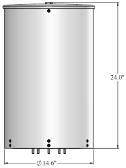
| Dimensions height/diameter, inches (mm) |
24.0/ 14.6 (609.6/ 370.8) |
| Antenna volume (cubic feet) | 2.32 |
| No. of RF input ports, connector type, and location | 18 x 4.3-10 RF, 1 x N-type GPS female, bottom |
| RF connector torque | 96 lbf·in (10.85 N·m or 8 lbf·ft) |
| Net antenna weight, lb (kg) | 31 (14.06) |
| Rated wind survival speed, mph (km/h) | 150 (241) |
| Frontal wind loading @ 160 km/h, lbf (N) | 30 (133) |
| Equivalent flat plate @ 100 mph and Cd=2, sq ft | 1.17/0.69 |
| Array topology | ||
|---|---|---|
|
9 sets of radiating arrays R1: 698-960 MHz Y1: 1695-2690 MHz Y2: 1695-2690 MHz P1: 3400-4200 MHz P2: 3400-4200 MHz O1: 5150-5925 MHz |
|
|
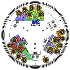
| Front view | End view |
|---|---|
 |
The 0 degree reference arrow corresponds to the 0 degree position in the antenna pattern file. Each antenna pattern file uses a top down orientation view (the patterns are viewed from the top of the antenna looking down). |
|
|
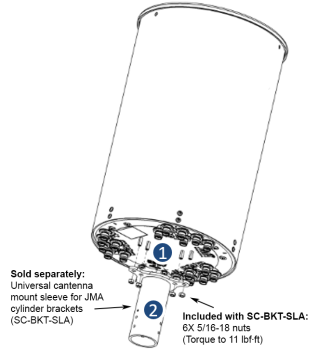
| End view details: 6 stud bolts for direct mount to the Universal Sleeve (SC-BKT-SLA) |
| Notes on mounting brackets | Example bracket configuration |
|---|---|
|
|
| Ordering information | ||||||
|---|---|---|---|---|---|---|
| Antenna model | Description | |||||
|
CYL2Q18GR-1xy R represents the selected Radome color of GRAY (G), BROWN (W), or BLACK (B) xy= fixed electrical tilt for 1695-2690 MHz in degrees |
2ft 18 Port OMNI antenna 4LB 8MB 4CBRS 2LAA with GPS | |||||
| Model | Radome color (R) | Tilt configuration | Radome color and tilt configuration description | |||
| R1 R2 | Y1-Y4 (x,y) | P1 P2 | O1 | |||
| CYL2Q18GG-122 | GRAY (G) | 0 | 2° | 0 | 0 | 2ft 18 Port antenna with GRAY Radome and 2° & 2° tilt settings |
| CYL2Q18GG-124 | 0 | Y1&Y2=2°,Y3&Y4=4° | 0 | 0 | 2ft 18 Port antenna with GRAY Radome and 2° & 4° tilt settings | |
| CYL2Q18GG-126 | 0 | Y1&Y2=2°,Y3&Y4=6° | 0 | 0 | 2ft 18 Port antenna with GRAY Radome and 2° & 6° tilt settings | |
| CYL2Q18GG-144 | 0 | 4° | 0 | 0 | 2ft 18 Port antenna with GRAY Radome and 4° & 4° tilt settings | |
| CYL2Q18GG-146 | 0 | Y1&Y2=4°,Y3&Y4=6° | 0 | 0 | 2ft 18 Port antenna with GRAY Radome and 4° & 6° tilt settings | |
| CYL2Q18GG-166 | 0 | 6° | 0 | 0 | 2ft 18 Port antenna with GRAY Radome and 6° & 6° tilt settings | |
| CYL2Q18GW-122 | BROWN (W) | 0 | 2° | 0 | 0 | 2ft 18 Port antenna with BROWN Radome and 2° & 2° tilt settings |
| CYL2Q18GW-124 | 0 | Y1&Y2=2°,Y3&Y4=4° | 0 | 0 | 2ft 18 Port antenna with BROWN Radome and 2° & 4° tilt settings | |
| CYL2Q18GW-126 | 0 | Y1&Y2=2°,Y3&Y4=6° | 0 | 0 | 2ft 18 Port antenna with BROWN Radome and 2° & 6° tilt settings | |
| CYL2Q18GW-144 | 0 | 4° | 0 | 0 | 2ft 18 Port antenna with BROWN Radome and 4° & 4° tilt settings | |
| CYL2Q18GW-146 | 0 | Y1&Y2=4°,Y3&Y4=6° | 0 | 0 | 2ft 18 Port antenna with BROWN Radome and 4° & 6° tilt settings | |
| CYL2Q18GW-166 | 0 | 6° | 0 | 0 | 2ft 18 Port antenna with BROWN Radome and 6° & 6° tilt settings | |
| CYL2Q18GB-122 | BLACK (B) | 0 | 2° | 0 | 0 | 2ft 18 Port antenna with BLACK Radome and 2° & 2° tilt settings |
| CYL2Q18GB-124 | 0 | Y1&Y2=2°,Y3&Y4=4° | 0 | 0 | 2ft 18 Port antenna with BLACK Radome and 2° & 4° tilt settings | |
| CYL2Q18GB-126 | 0 | Y1&Y2=2°,Y3&Y4=6° | 0 | 0 | 2ft 18 Port antenna with BLACK Radome and 2° & 6° tilt settings | |
| CYL2Q18GB-144 | 0 | 4° | 0 | 0 | 2ft 18 Port antenna with BLACK Radome and 4° & 4° tilt settings | |
| CYL2Q18GB-146 | 0 | Y1&Y2=4°,Y3&Y4=6° | 0 | 0 | 2ft 18 Port antenna with BLACK Radome and 4° & 6° tilt settings | |
| CYL2Q18GB-166 | 0 | 6° | 0 | 0 | 2ft 18 Port antenna with BLACK Radome and 6° & 6° tilt settings | |
| Small Cell solutions and mounting systems (sold separately) | |||
|---|---|---|---|
| Side Arm Mounting System | SC-BKT-SA-(color) | Wide Diameter Pole | SC-BKT-WTPE-(color) |
| Steel Pole Mounting System | SC-BKT-SLA (color) | ||
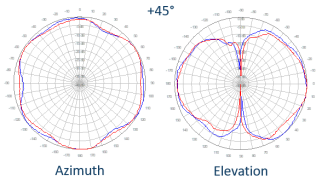
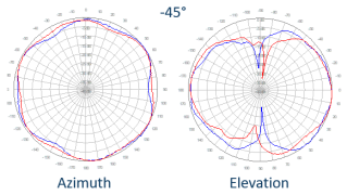
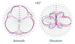
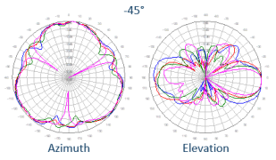
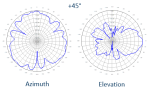
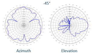
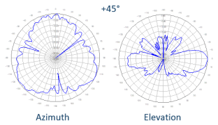
| Polar patterns | ||
|---|---|---|
|
R1-R2, 0° Tilt
|
||

|
|
|
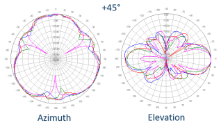
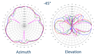
| Y1-Y4, 2° Tilt
|
||
|
|
|
|
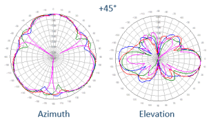
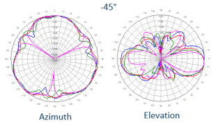
 Y1-Y4, 4° Tilt Y1-Y4, 4° Tilt
|
||
|
|
|
| Y1-Y4, 6° Tilt
|
||
|
|
|

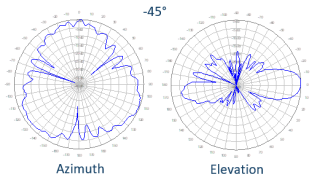
| Polar patterns | ||
|---|---|---|
|
P1-P2, 0° Tilt
|
||

|
|
|
| O1, 0° Tilt
|
||
|
|
|
|

V3.0
| ©2026 JMA Wireless. All rights reserved. All products, company names, brands, and logos are trademarks™ or registered® trademarks of their respective holders. All specifications are subject to change without notice. +1 315.431.7100 customerservice@jmawireless.com |