|
|

|
16-port 2 ft 240° cylinder antenna with RET-controlled HB from 1695-2700 MHz: 4 ports 698-960 MHz, 4 ports 1695-2690 MHz, 4 ports 3550-3700 MHz, and 4 ports 5150-5925 MHz |
||
|---|---|---|
|

|
|

| Electrical specification (min/max) |
|
||||||||
|---|---|---|---|---|---|---|---|---|---|
| Frequency bands, MHz | 698-798 | 824-894 | 1695-1880 | 1850-1990 | 1920-2180 | 2300-2400 | 2496-2690 | ||
| Polarization | ± 45° | ± 45° | |||||||
| Average gain over all tilts, dBi | 3.6 | 3.9 | 9.8 | 10.2 | 10.4 | 10.7 | 10.8 | ||
| Horizontal beamwidth (HBW), degrees1 | 240° | 240° | |||||||
| Vertical beamwidth (VBW), degrees1 | 70° | 63° | 15.0° | 14.3° | 14.1° | 12.6° | 11.5° | ||
| Electrical downtilt (EDT) range, degrees | 2° | 2-8° (RET) | |||||||
| Cross-polar isolation, port-to-port, dB1 | 25 | 25 | 25 | 25 | 25 | 25 | 25 | ||
| Max VSWR / return loss, dB | 1.5:1 / -14.0 | 1.5:1 / -14.0 | |||||||
| Max PIM, 3rd order 2x20W carrier, dBc | -153 | -153 | |||||||
| Maximum input power per port, watts | 250 | 125 | |||||||
| Maximum composite power, watts | 900 | ||||||||
| Electrical specification (min/max) |
|
|||
|---|---|---|---|---|
| Frequency bands, MHz | 3550-3700 | 5150-5925 | ||
| Polarization | ± 45° | ± 45° | ||
| Average gain, dBi | 6.1 | 4.2 | ||
| Horizontal beamwidth (HBW), degrees1 | 240° | 240° | ||
| Vertical beamwidth (VBW), degrees1 | 29° | 28.9° | ||
| Electrical downtilt (EDT) range, degrees | 0° | |||
| Cross-polar isolation, port-to-port, dB1 | 25 | 25 | ||
| Max VSWR / return loss, dB | 1.5:1 / -14.0 | 1.5:1 / -14.0 | ||
| Max PIM, 3rd order 2x20W carrier, dBc | N/A | |||
| Maximum total input power, watts | 50 | 10 | ||
| 1 Typical value over frequency and tilt. | Note: To comply with FCC Title 47 Part 15 U-NII 1, the vertical beam upper side lobe at 5150-5250 MHz < -12 dB at > 30° above horizon |
| Mechanical specifications | |
|---|---|
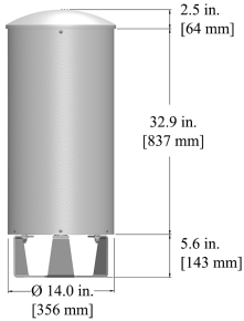
| Dimensions height/diameter, inches (mm) | 35.4/ 14 (899.2/ 355) |
| Antenna volume (cubic feet) | 2.98 |
| No. of RF input ports, connector type, and location | 16 x 4.3-10 female, bottom |
| RF connector torque | 96 lbf·in (10.85 N·m or 8 lbf·ft) |
| Net antenna weight, lb (kg) | 35 (15.9) |
| Rated wind survival speed, mph (km/h) | 150 (241) |
| Frontal wind loading @ 160 km/h, lbf (N) | 58.7 (261.2) |
| Equivalent flat plate @ 100 mph and Cd=2, sq ft | 1.17 |
| Front view | End view |
|---|---|
 |
The 0 degree reference arrow corresponds to the 0 degree position in the antenna pattern file. Each antenna pattern file uses a top down orientation view (the patterns are viewed from the top of the antenna looking down). |
 |
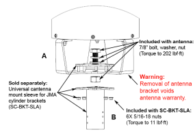
| Notes on cylinder brackets | Mounting details |
|---|---|
|
|
| Small Cell solutions and mounting systems (sold separately) | |||
|---|---|---|---|
| Side Arm Mounting System | SC-BKT-SA-(color) | Wide Diameter Pole | SC-BKT-WTPE-(color) |
| Steel Pole Mounting System | SC-BKT-SLA (color) | ||
| Ordering information | |
|---|---|
| Antenna model | Description |
| CX16OMI224-1H | 2F X-Pol 16-port OMNI 240°, 1695-2690 MHz 2-8° RET, 4.3-10 |
| Optional accessories | |
| AISG cables | M/F cables for AISG connections |
| PCU-1000 RET controller | Stand-alone controller for RET control and configurations |
| Remote electrical tilt (RET 1000) information | |
|---|---|
| RET location | Integrated into antenna |
| RET interface connector type | 8-pin AISG connector per IEC 60130-9 |
| RET connector torque | Min 0.5 N·m to max 1.0 N·m (hand pressure & finger tight) |
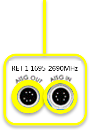
| RET interface connector quantity | 2 pairs of AISG male/female connectors |
| RET interface connector location | Bottom of the antenna |
| Total no. of internal RETs high bands | 1 |
| RET input operating voltage, vdc | 10-30 |
| RET max power consumption, idle state, W | ≤ 2.0 |
| RET max power consumption, normal operating conditions, W | ≤ 13.0 |
| RET communication protocol | AISG 2.0 / 3GPP |
| RET topology | |||||||
|---|---|---|---|---|---|---|---|
| A single RET device controls all 3 sectors via the designated external AISG connector as shown below: | |||||||
|
|||||||
|
|||||||
| Array topology | ||
|---|---|---|
|
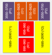
8 sets of radiating arrays R1: 698-960 MHz R2: 698-960 MHz Y1: 1695-2690 MHz Y2: 1695-2690 MHz P1: 3550-3700 MHz P2: 3550-3700 MHz O1: 5150-5925 MHz O2: 5150-5925 MHz |
 |
|
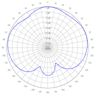
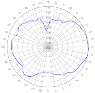
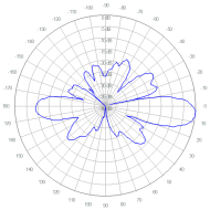
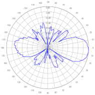
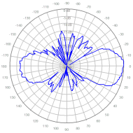
| Polar patterns | ||
|---|---|---|
| Horizontal | Vertical | |
| 698-894 MHz |
|
|
| 1695-2690 MHz |
|
|
| 3550-3700 MHz |
|
|
| 5150-5925 MHz |
|
|
V2.0
| ©2026 JMA Wireless. All rights reserved. All products, company names, brands, and logos are trademarks™ or registered® trademarks of their respective holders. All specifications are subject to change without notice. +1 315.431.7100 customerservice@jmawireless.com |